How To Connect Water Flow Sensor Through Arduino Using LED And Buzzer Presentation
| Introduction | ||
|---|---|---|
| In this presentation, we will learn how to connect a water flow sensor through Arduino using an LED and buzzer. This setup can be useful in applications such as monitoring water usage or detecting leaks. By the end of this presentation, you will have a clear understanding of the necessary steps to set up this system. | ||
| 1 | ||
| Components Required | ||
|---|---|---|
| Arduino board: We will use an Arduino Uno for this project. Water flow sensor: Choose a sensor suitable for your application. LED: A simple indicator to show the water flow status. | ||
| 2 | ||

| Wiring the Water Flow Sensor | ||
|---|---|---|
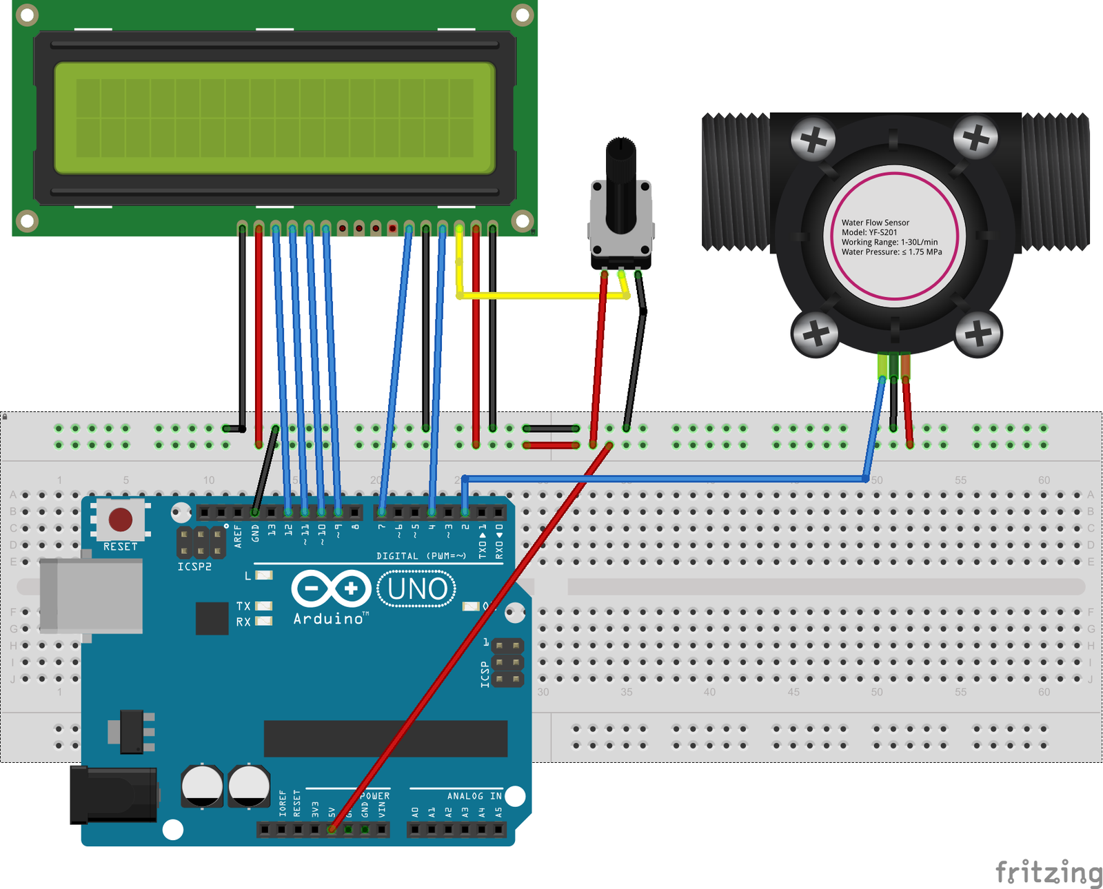
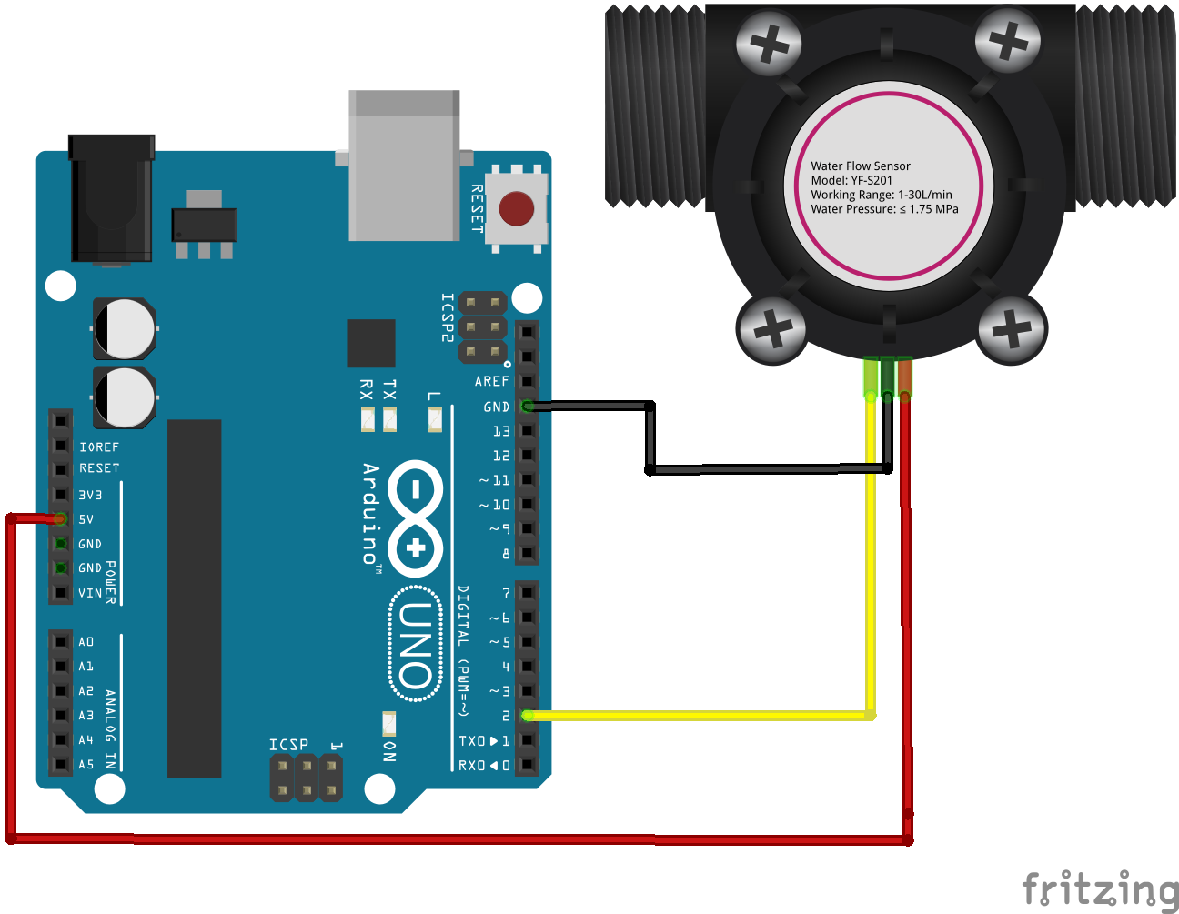
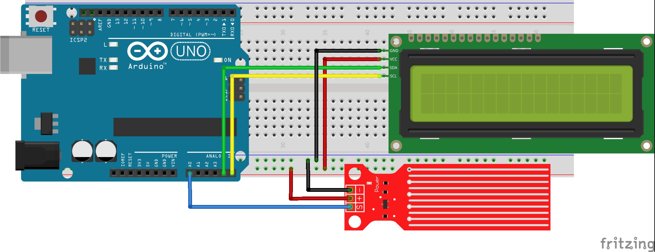
| Connect the VCC pin of the water flow sensor to the 5V pin of the Arduino. Connect the GND pin of the sensor to the GND pin of the Arduino. Connect the signal pin of the sensor to any digital pin of the Arduino, for example, pin 2. | ||
| 3 | ||
| Adding the LED | ||
|---|---|---|
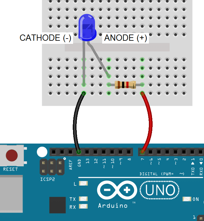
| Connect the longer leg (anode) of the LED to a current-limiting resistor (220-470 ohms). Connect the other end of the resistor to any digital pin of the Arduino, for example, pin 3. Connect the shorter leg (cathode) of the LED directly to the GND pin of the Arduino. | ||
| 4 | ||
| Adding the Buzzer | ||
|---|---|---|
| Connect the positive (anode) pin of the buzzer to a digital pin of the Arduino, for example, pin 4. Connect the negative (cathode) pin of the buzzer to the GND pin of the Arduino. Your third bullet | ||
| 5 | ||
| Arduino Code Overview | ||
|---|---|---|
| Install the necessary libraries for the water flow sensor (if required). Initialize the digital pins for the LED and buzzer in the setup() function. Read the sensor's signal in the loop() function and map the values to appropriate flow rates. | ||
| 6 | ||
| Arduino Code - Reading the Sensor | ||
|---|---|---|
| Use the pulseIn() function to measure the time it takes for a pulse to travel through the sensor. Calculate the flow rate using the formula provided in the sensor's datasheet. Store the flow rate value in a variable for further processing. | ||
| 7 | ||
| Arduino Code - LED and Buzzer Control | ||
|---|---|---|
| Use conditional statements to check the flow rate against predefined thresholds. If the flow rate is below a certain threshold, turn off the LED and buzzer. If the flow rate exceeds a certain threshold, turn on the LED and buzzer to indicate the high flow rate. | ||
| 8 | ||

| Testing and Troubleshooting | ||
|---|---|---|
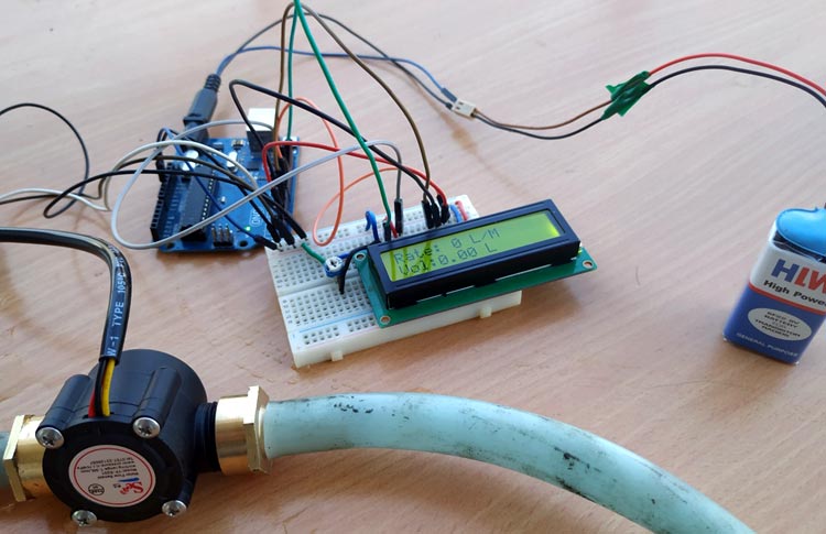
| Upload the code to the Arduino and verify the connections. Test the system by allowing water to flow through the sensor and observe the LED and buzzer behavior. If the system does not work as expected, double-check the wiring, code, and sensor specifications. | ||
| 9 | ||

| Conclusion | ||
|---|---|---|
| Connecting a water flow sensor through Arduino using an LED and buzzer is a straightforward process. With the knowledge gained from this presentation, you can build your own water flow monitoring system. Remember to consider safety precautions and adapt the code and setup based on your specific requirements. | ||
| 10 | ||