Design And Simulation Of Rectangular Microstrip Patch Antenna For 80 GHz Presentation
| Introduction | ||
|---|---|---|
| The demand for high-frequency applications has led to the need for efficient antennas operating at 80 GHz. Rectangular microstrip patch antennas are commonly used due to their compact size and ease of fabrication. This presentation will discuss the design and simulation of a rectangular microstrip patch antenna for 80 GHz. | ||
| 1 | ||

| Antenna Design Considerations | ||
|---|---|---|
| The design of an 80 GHz microstrip patch antenna requires careful consideration of various factors such as substrate material, patch dimensions, and feeding techniques. The substrate material should have a low dielectric constant and loss tangent to minimize signal losses. The patch dimensions and shape should be optimized to achieve the desired resonant frequency and radiation pattern. | ||
| 2 | ||
| Patch Geometry and Dimensions | ||
|---|---|---|
| The patch geometry for an 80 GHz microstrip patch antenna is typically rectangular. The dimensions of the patch, such as length and width, are determined based on the desired resonant frequency. The length and width of the patch can be adjusted to achieve the desired impedance matching and bandwidth. | ||
| 3 | ||

| Substrate Selection | ||
|---|---|---|
| The choice of substrate material plays a crucial role in the performance of an 80 GHz microstrip patch antenna. Substrates with low dielectric constant, such as polytetrafluoroethylene (PTFE) or Rogers RT/ Duroid, are preferred to reduce signal losses. The substrate should also have a low loss tangent to minimize power dissipation. | ||
| 4 | ||
| Feeding Techniques | ||
|---|---|---|
| Different feeding techniques can be used to excite the patch antenna at 80 GHz. Microstrip-line feeding is commonly used, where a microstrip transmission line is used to feed the antenna. Another option is proximity coupling, where a probe is placed near the patch to couple the signal. | ||
| 5 | ||

| Simulation Tools | ||
|---|---|---|
| Various electromagnetic simulation tools, such as CST Microwave Studio, Ansys HFSS, or Sonnet, can be used for the design and simulation of microstrip patch antennas. These tools allow for accurate analysis of the antenna's performance, including radiation pattern, return loss, and gain. Simulation results can be used to optimize the design parameters and ensure the desired performance at 80 GHz. | ||
| 6 | ||
| Impedance Matching | ||
|---|---|---|
| Impedance matching is essential to maximize power transfer between the antenna and the transmission line. Techniques such as adjusting the patch dimensions or using matching networks can be employed to achieve impedance matching. Simulation tools can aid in optimizing the matching network components and placement. | ||
| 7 | ||

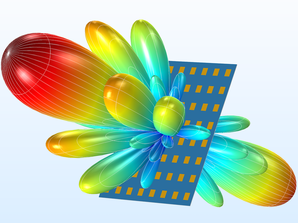
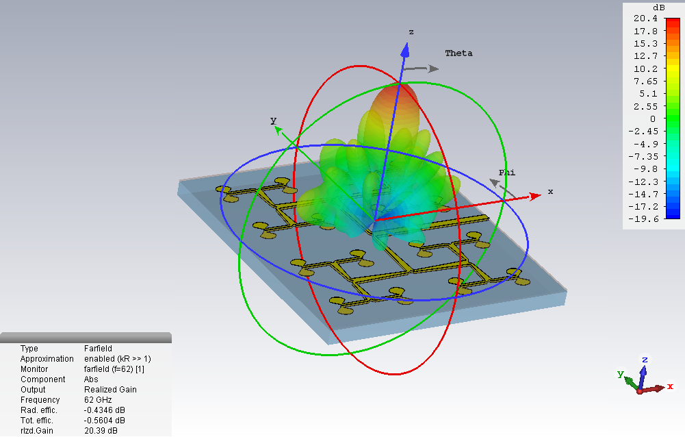
| Radiation Pattern Analysis | ||
|---|---|---|
| The radiation pattern of a microstrip patch antenna at 80 GHz needs to be analyzed to ensure the desired coverage and gain. Simulation tools can provide detailed radiation pattern plots, illustrating the antenna's performance in terms of beamwidth, directivity, and side lobes. Adjustments to the patch dimensions or feeding techniques can be made to achieve the desired radiation characteristics. | ||
| 8 | ||
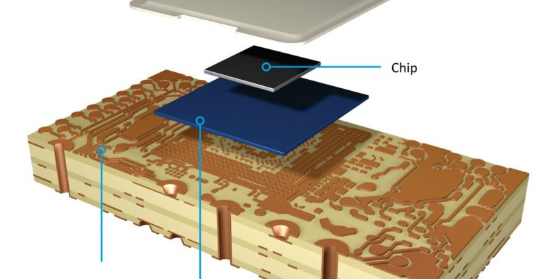
| Fabrication and Testing | ||
|---|---|---|
| Once the design and simulation are completed, the fabrication of the microstrip patch antenna can be carried out. Techniques such as photolithography, etching, and deposition are used to create the antenna structure on the chosen substrate. After fabrication, the antenna should be tested to validate its performance and compare it with the simulation results. | ||
| 9 | ||

| Conclusion | ||
|---|---|---|
| Designing and simulating a rectangular microstrip patch antenna for 80 GHz requires careful consideration of various factors such as substrate selection, patch dimensions, feeding techniques, and impedance matching. Simulation tools play a crucial role in optimizing the design and ensuring the desired performance. Fabrication and testing are necessary to validate the antenna's performance and compare it with the simulation results. | ||
| 10 | ||
