Analysis Of Half Wave Rectifier Presentation
| Introduction to Half Wave Rectifier | ||
|---|---|---|
| The half wave rectifier is a simple circuit that converts AC input voltage into pulsating DC output voltage. It is called a half wave rectifier because it only rectifies one half of the input waveform. The rectification is achieved using a diode, which allows current to flow in only one direction. | ||
| 1 | ||
| Circuit Diagram of Half Wave Rectifier | ||
|---|---|---|
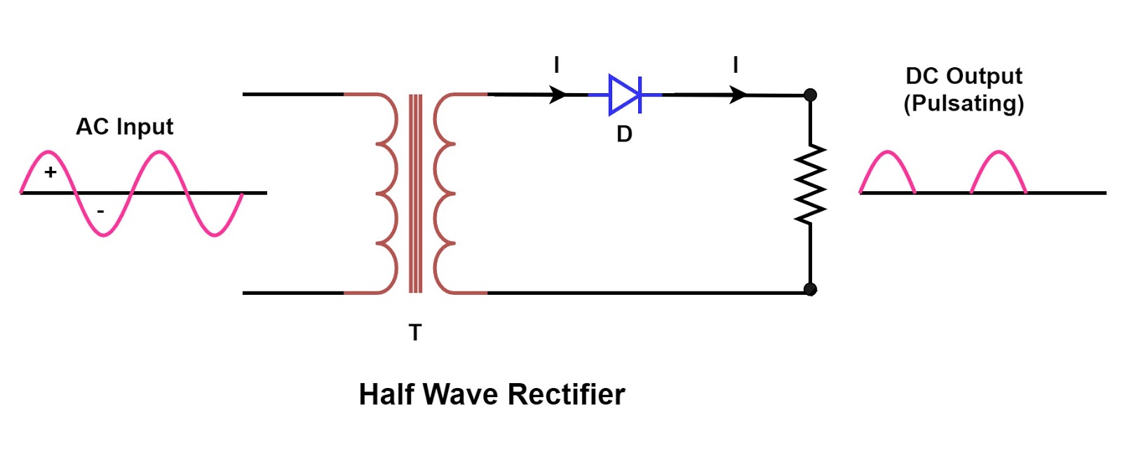
| The circuit consists of an AC source, a diode, and a load resistor. The AC source provides the input voltage, which is typically a sinusoidal waveform. The diode allows current to flow in the forward direction and blocks it in the reverse direction. | ||
| 2 | ||
| Operation of Half Wave Rectifier | ||
|---|---|---|
| During the positive half-cycle of the input voltage, the diode is forward-biased and conducts current. The current flows through the load resistor, resulting in a positive half-cycle output voltage across the load. During the negative half-cycle, the diode is reverse-biased and blocks current flow, resulting in zero output voltage. | ||
| 3 | ||
| Output Waveform of Half Wave Rectifier | ||
|---|---|---|
| The output waveform of a half wave rectifier is a pulsating DC waveform. It consists of only the positive half-cycles of the input waveform. The output voltage is equal to the peak value of the input voltage. | ||
| 4 | ||
| Ripple Voltage in Half Wave Rectifier | ||
|---|---|---|
| The pulsating DC output of a half wave rectifier contains ripple voltage. Ripple voltage is the AC component superimposed on the DC output voltage. It is caused by the fact that the diode only conducts during one-half of the input waveform. | ||
| 5 | ||
| Calculation of DC Output Voltage | ||
|---|---|---|
| The DC output voltage of a half wave rectifier can be calculated using the peak value of the input voltage. The peak value of the input voltage is multiplied by the diode's forward voltage drop. The result is reduced by the voltage drop across the load resistor to obtain the DC output voltage. | ||
| 6 | ||
| Efficiency of Half Wave Rectifier | ||
|---|---|---|
| The efficiency of a half wave rectifier is the ratio of the DC power output to the AC power input. It is typically low due to the presence of ripple voltage and the voltage drop across the diode. The efficiency can be improved by using a smoothing capacitor to reduce ripple voltage. | ||
| 7 | ||
| Advantages of Half Wave Rectifier | ||
|---|---|---|
| Simple circuit design and low cost. Suitable for low-power applications. Can be easily analyzed and understood. | ||
| 8 | ||
| Disadvantages of Half Wave Rectifier | ||
|---|---|---|
| Low efficiency due to the presence of ripple voltage. Only utilizes half of the input waveform, resulting in wasted power. Not suitable for high-power applications. | ||
| 9 | ||
| Applications of Half Wave Rectifier | ||
|---|---|---|
| Battery chargers and power supplies. Radio demodulation. Signal rectification in analog circuits. (Note: The above content is a suggestion, and you can modify and expand upon it as per your requirements and knowledge on the topic.) |  | |
| 10 | ||


